
Direct Answer (TL;DR)
Plugging certified balcony solar into an outdoor receptacle is intrinsically safe because UL 1741UL 1741The North American safety standard for distributed generation inverters, certifying rapid automated shutdown during grid outages.UL 1741 Safety Guide → microinverters cease power generation within milliseconds if disconnected. Outdoor safety requires meeting National Electrical Code standards. Your outlet must feature an NEC 406.9NEC 406.9National Electrical Code rules mandating weatherproof and extra-duty while-in-use covers for receptacles in damp or wet outdoor locations.NFPA Code Directory → extra-duty while-in-use weatherproof cover, functional NEC 210.8NEC 210.8National Electrical Code regulations governing ground-fault circuit-interrupter protection for personnel across outdoor dwelling unit circuits.NFPA Safety Standards → GFCI protection, and sound circuit ampacity.
Never route extension cords through windows or doors, as this violates NEC 400.12NEC 400.12National Electrical Code regulations strictly prohibiting running flexible appliance cords through windows, doors, walls, or holes in ceilings.NFPA Flexible Cords → and creates pinching hazards. Protect ground cables inside protective conduit against lawnmowers and rodents. Follow statutory capacity rules ranging from standard 800 W systems to Colorado’s 1,920 W cap.
Balcony solar kits are designed as simple appliances. You mount lightweight panels to an apartment railing, attach a microinverter, and insert a three-prong plug into an outdoor wall outlet.
In Europe, more than one million households operate plug-in solar with an immaculate safety record. Zero structural fires or line-worker electrocutions have occurred from certified hardware.
In the United States, however, household wiring operates at 120 V rather than 230 V. Outdoor electrical boxes face rain, freezing snow, coastal salt spray, and summer heat. Many American convenience circuits also share wiring across multiple rooms.
Understanding electrical safety standards turns anxiety into practical confidence. This guide explains mandatory National Electrical Code (NEC) rules, demystifies inverter safety, reviews DIY racks and ideal placement, safeguards wiring from lawnmowers and pets, and details low-cost upgrades that maximize protection.
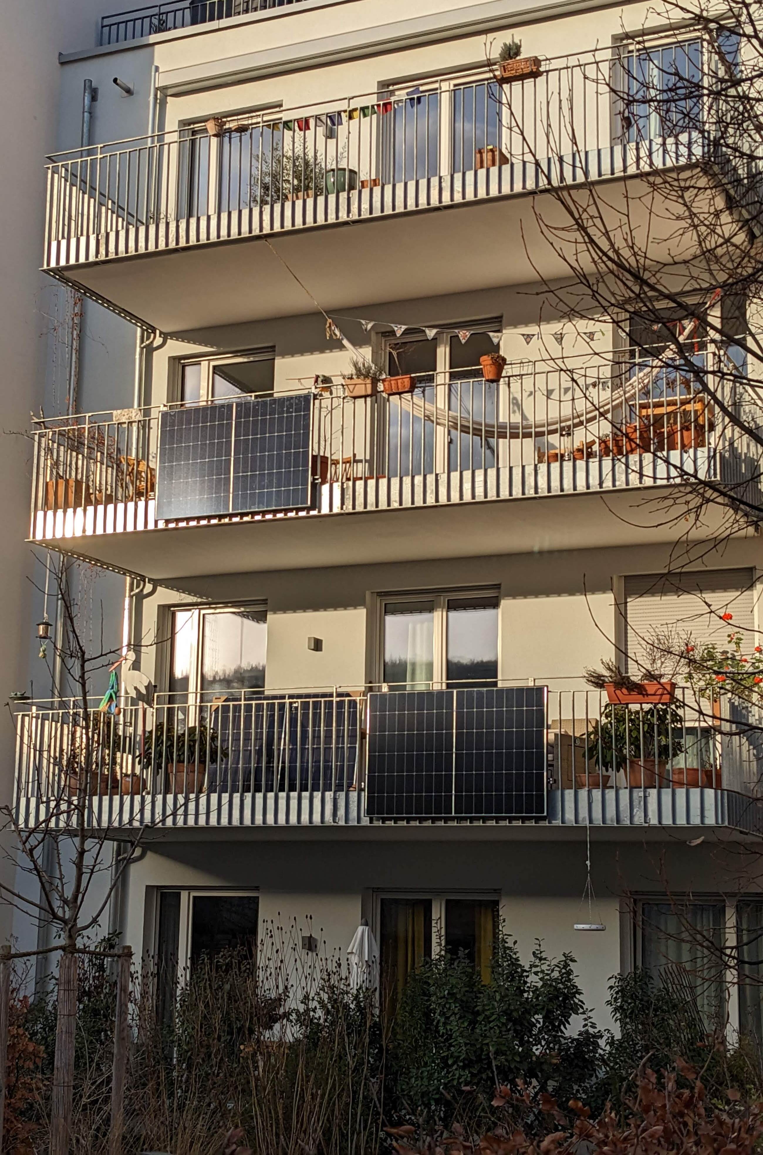 Standard outdoor residential receptacles require weatherproof enclosures and proper
branch circuit capacity for safe, continuous solar injection. Photo:
BalconySolar.org.
Standard outdoor residential receptacles require weatherproof enclosures and proper
branch circuit capacity for safe, continuous solar injection. Photo:
BalconySolar.org.
1. Demystifying plug-in solar electrical physics
The most common fear among prospective buyers is electrical shock: What happens if someone pulls the plug while the sun shines? Will backfed power energize the exposed metal prongs?
Certified grid-tied solar hardware cannot shock you when unplugged. This protection is built directly into the microinverter through automated anti-islandingAnti-Islanding ProtectionA mandatory safety mechanism that de-energizes inverter AC output within milliseconds whenever utility grid power drops or the plug is disconnected.Anti-Islanding Guide → circuitry.
Under IEEE 1547 and UL 1741 standards, an inverter continuously monitors the external electrical grid. It requires an active utility voltage sine wave to generate power.
The moment you pull the plug from the receptacle, grid voltage drops to zero. The microinverter internal relays open in less than 200 ms–typically within 16 to 30 ms. By the time the metal prongs clear the socket face, they are completely de-energized.
Similarly, during a utility blackout, plug-in solar stops producing power instantly. Line workers repairing local neighborhood distribution lines face zero backfeed risk from certified systems.
For complete state-level interconnection policies, see our guide on utility permission for plug-in solar.
2. Navigating mandatory National Electrical Code requirements
While certified equipment protects against electrical shock, your outdoor wall receptacle must satisfy the National Electrical Code (NEC). Several specific articles govern outdoor plug-in solar installations:
NEC 406.9(B)(1): Extra-duty while-in-use covers
Standard indoor wall outlets use flat decorative faceplates. Traditional outdoor outlets often carry shallow, spring-loaded metallic flaps that flip closed only when nothing is plugged in.
NEC 406.9(B)(1) mandates that all 15 A and 20 A receptacles installed in wet locations must feature an extra-duty while-in-use cover. This deep enclosure shields the connection from rain, snow, and sprinklers even while an appliance cord remains continuously plugged in.
Flat flip covers leave the plug exposed to driving rain when occupied. Water entering a live socket causes corrosion, tracking faults, and electrical shorts. A clear, hinged polycarbonate bubble cover satisfies NEC 406.9(B)(1) and keeps moisture out.
NEC 210.8(A)(3): GFCI protection for outdoor receptacles
Outdoor receptacles on residential buildings must have Ground-Fault Circuit-Interrupter (GFCIGround-Fault Circuit-InterrupterA fast-acting circuit interrupter that disconnects power when it detects small current imbalances between hot and neutral conductors, preventing severe electric shocks.GFCI Compatibility Guide →) protection under NEC 210.8(A)(3).
A GFCI device monitors the balance of electrical current flowing between hot and neutral conductors. If as little as 4 mA to 6 mA of current leaks to ground, the GFCI trips within 25 ms to prevent lethal shock.
Modern UL 1741 microinverters operate harmoniously with Class A GFCI receptacles. Older GFCI outlets, however, may suffer from worn mechanical springs or degraded electronic sensors. For detailed troubleshooting and nuisance tripping diagnosis, consult our guide on GFCI outlet plug-in solar compatibility. Test your outdoor GFCI outlet using its integrated test and reset buttons before connecting solar hardware.
NEC 400.12: Prohibitions on flexible cords through windows
Renters lacking an outdoor receptacle often consider running an ordinary extension cord from an indoor living room outlet, through a cracked window or sliding door, out onto the balcony.
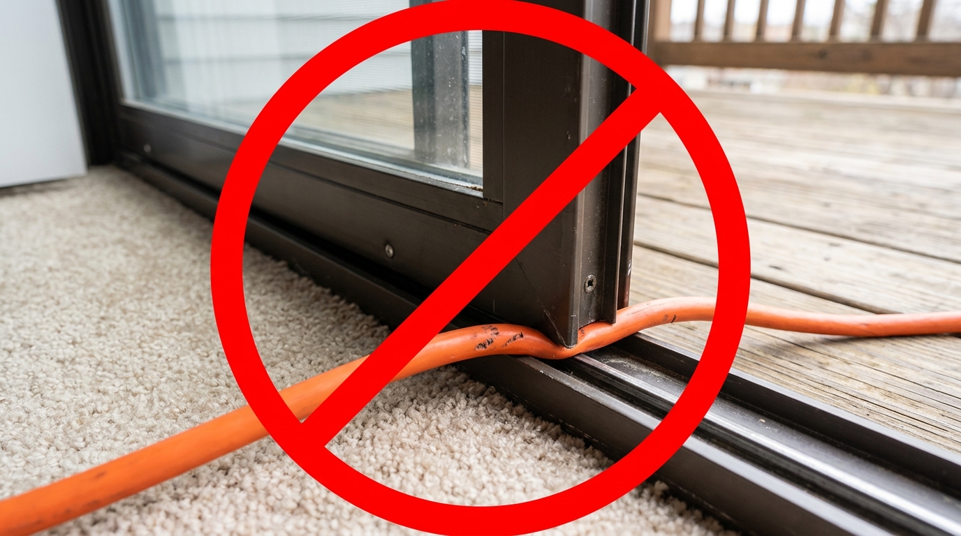 Hazardous cord routing through a sliding door opening. Crushing an extension cord
under door tracks violates NEC 400.12, damages conductor strands, and creates severe
electrical fire hazards. Photo: BalconySolar.org.
Hazardous cord routing through a sliding door opening. Crushing an extension cord
under door tracks violates NEC 400.12, damages conductor strands, and creates severe
electrical fire hazards. Photo: BalconySolar.org.
NEC 400.12 explicitly prohibits running flexible cords through doorways, windows, walls, ceilings, or structural building envelopes. Flexible cords are designed solely for temporary portable appliances, not as permanent branch wiring substitutes.
Crushing an electrical cable within a window or sliding door frame triggers four distinct physical hazards:
- Conductor Strand Severance: Sliding door tracks exert heavy mechanical force on flexible cords. Crushing copper strands reduces conductor cross-sectional area, creating localized electrical resistance and intense heat under continuous solar generation.
- Thermal Arc Faults: Pinched cords routinely rest against synthetic carpet, wooden trim, or curtains. Damaged conductor insulation leads to arcing faults that ignite nearby combustible household materials.
- Envelope Weatherization Failure: Leaving sliding doors or windows cracked breaks building thermal seals. Wind-driven rain enters wall sill cavities, causing water damage and hidden mold growth.
- Insurance Policy Invalidation: Running unlisted extension cords through building envelopes violates residential fire codes. In the event of an electrical fire, insurers frequently deny property damage claims due to unpermitted wiring.
[Sliding Patio Door / Window Sash: Heavy Downward Mechanical Force]
                                   |
                                   v
====[Flexible Outer Cord Jacket Crushed, Flattened, and Chafed]====
----(Internal Copper Strands Severed / Conductor Area Reduced)----
                                   |
                                   v
[Localized High-Resistance Hot Spot Formed Under Load (I^2 * R)]
                                   |
                                   +--> Thermal Melting of Insulation
                                   +--> Electric Arcing Across Conductors
                                   +--> Ignition of Combustible Carpeting
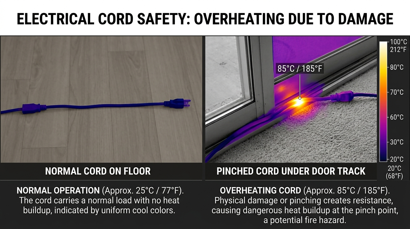 Thermal imaging reveals the invisible danger of NEC 400.12 cord pinching. At left,
an undamaged conductor carrying 6.7 A operates at a normal 25 °C (77 °F). At right,
copper strand severance under a door track causes high electrical resistance,
generating a dangerous 85 °C (185 °F) hot spot on combustible carpet. Photo:
BalconySolar.org.
Thermal imaging reveals the invisible danger of NEC 400.12 cord pinching. At left,
an undamaged conductor carrying 6.7 A operates at a normal 25 °C (77 °F). At right,
copper strand severance under a door track causes high electrical resistance,
generating a dangerous 85 °C (185 °F) hot spot on combustible carpet. Photo:
BalconySolar.org.
If your rental property or condominium lacks an exterior receptacle, do not run cords through windows. Instead, consider three safe alternatives:
- Landlord-Approved Receptacle Installation: Ask your property manager to authorize a licensed electrician installing an outdoor WR GFCI receptacle. This upgrade permanently increases property value.
- Dedicated Battery Storage Buffer: Place an outdoor-rated portable power station on your balcony to capture solar energy, then bring the battery inside to charge household electronics safely.
- Approved Low-Profile Passthrough Ribbons: In jurisdictions where permitted by local building officials, use specialized flat multi-conductor bridge strips engineered specifically for window sash clearances without pinching conductors.
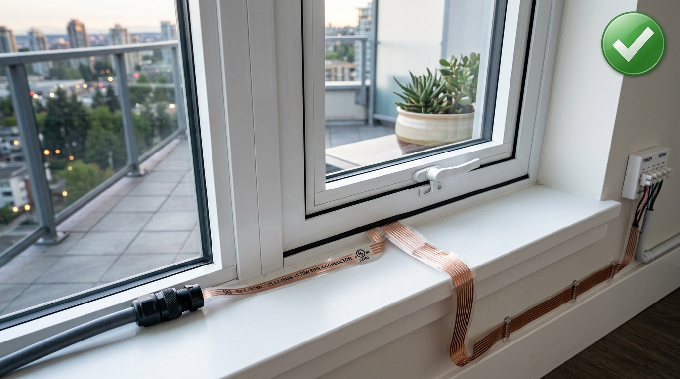 Code-compliant window passthrough alternative. An ultra-thin multi-conductor flat
ribbon cable slips beneath the closed window sash, preserving weather seals without
pinching internal copper conductors. Photo: BalconySolar.org.
Code-compliant window passthrough alternative. An ultra-thin multi-conductor flat
ribbon cable slips beneath the closed window sash, preserving weather seals without
pinching internal copper conductors. Photo: BalconySolar.org.
For lease compliance strategies and zero-drill alternatives, consult our guide on renter balcony solar landlord permission.
NEC 240.4(D) and NEC 705.12: Conductor overcurrent and busbar loading
German 230 V electrical circuits deliver 3.5 A from an 800 W inverter into a 16 A branch. Ample thermal buffer remains on the conductor.
In the United States, standard convenience circuits operate at 120 V. A standard 800 W microinverter outputs 6.67 A into the circuit.
At 120 V, 800 W divided by 120 V equals 6.67 A. This current represents nearly half of the total 15 A continuous capacity of standard residential 14 AWG copper wiring.
Under NEC 240.4NEC 240.4National Electrical Code rules setting conductor overcurrent protection limits: 15 A for 14 AWG and 20 A for 12 AWG copper wire.NFPA Conductor Ampacity → and NEC 705.12NEC 705.12National Electrical Code rules governing point of connection and busbar ampacity limits for backfed distributed power generation.NFPA Distributed Generation →, circuit breakers protect wiring from drawing excessive current from the grid panelboard. Backfed generation onto a branch circuit creates a potential conductor overload scenario:
[Main Panelboard 15A Breaker]
            |
            | (14 AWG Copper Wire - Rated 15A)
            |
            v
[Balcony Solar Outlet: +6.67A Injection]
            |
            | (Conductor Segment Between Solar and Load)
            |
            v
[Downstream Appliance Load: 18.0A Total Draw]
Consider what occurs on this shared branch:
- Downstream appliances (such as a 1,500 W portable space heater and a television) draw 18.0 A.
- The balcony solar microinverter injects 6.67 A directly into the circuit wiring.
- The main panelboard breaker supplies only the difference: 18.0 A minus 6.67 A equals 11.33 A.
- The 15 A breaker registers 11.33 A, well below its trip threshold. The breaker does not trip.
- However, the physical wire segment between the solar outlet and the appliances carries the full 18.0 A.
Operating 18.0 A through 14 AWG wire exceeds the thermal safety limit defined by NEC 240.4(D). Over hours of continuous operation, this hidden overload degrades wire insulation behind drywall.
To eliminate this hazard, never run heavy heating or cooling appliances on the same branch circuit as your balcony solar kit.
For system capacity choices and tariff economics, see our balcony solar sizing and payback guide.
3. Comparing statutory wattage limits across state and international laws
Legislatures establish specific power limits to balance consumer affordability with electrical grid safety. Three primary statutory tiers define the plug-in solar landscape:
The 800 W European and international benchmark
In Germany, the federal Solarpaket I legislation established 800 W AC as the nationwide threshold for simplified plug-in solar. An 800 W system injects 3.48 A on European 230 V circuits. In the United States, several state bills propose 800 W as a standard baseline, injecting 6.67 A onto standard 120 V household wiring.
The 1,200 W plug-in tier (Maryland and Utah)
Maryland enacted Chapter 353 (HB 1532) and Utah passed HB 340, establishing a generous 1,200 W threshold for plug-in solar devices.
Under these statutes, qualifying systems up to 1,200 W need no utility approval. Utah bars utility fees and extra equipment. Maryland allows one system per electric meter for residential use. It bars fees related to feeding power back into the electric system, and extra equipment other than an automatic locking disconnect switch the customer pays for when the system requires one. At 120 V, a 1,200 W microinverter outputs 10.0 A, operating smoothly on standard 15 A or 20 A branch circuits.
Colorado HB26-1007: a 1,920 W cap with a 391 W exemption
Colorado’s HB26-1007 covers a single photovoltaic system per address that supplies no more than 1,920 W to the grid and is labeled and listed by a nationally recognized testing laboratory. A customer may not connect more than one device to a single wall outlet, and the act sets no dedicated-circuit requirement.
- 391 W or less: These devices are exempt from the state’s solar installation supervision rules and from code or listing provisions that would require alterations to the building’s electrical wiring. At 120 V, 391 W is 3.26 A.
- Up to 1,920 W: From January 1, 2027, a device with more than 391 W of output may not be sold, leased or rented in Colorado unless it is UL labeled and listed. At 120 V, 1,920 W is 16.0 A, more than a 15 A branch circuit is rated to carry.
Check your state’s enacted rules using our state comparison tool or read our statutory summary Is Balcony Solar Legal in My State.
4. Best locations for panel placement and common DIY rack types
Where you place your panels dictates both energy harvest and physical safety. Different residential settings call for specific mounting designs:
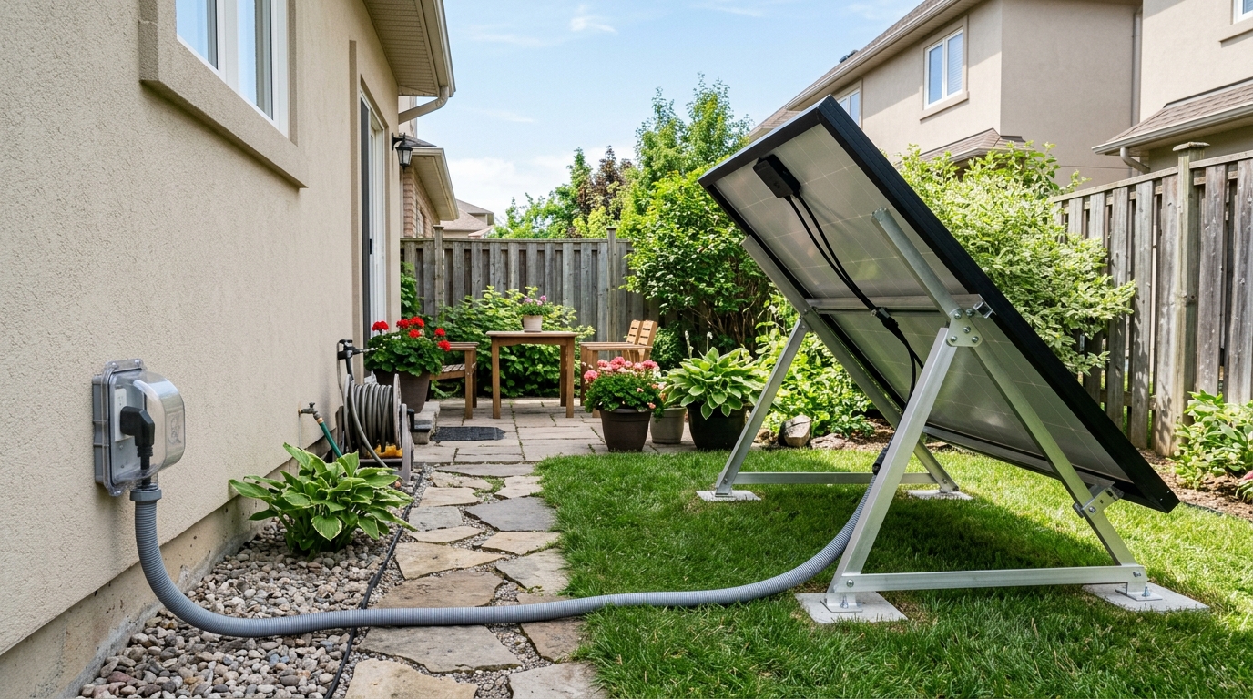 Residential patio ground mount featuring an adjustable aluminum triangular rack,
protective cable conduit, and an extra-duty while-in-use bubble cover. Photo:
BalconySolar.org.
Residential patio ground mount featuring an adjustable aluminum triangular rack,
protective cable conduit, and an extra-duty while-in-use bubble cover. Photo:
BalconySolar.org.
Prime placement locations
Four micro-locations work effectively for residential plug-in systems:
- Balcony Railings: The classic urban choice. South-facing railings offer unobstructed sky views. East-west facing railings capture morning and evening production shoulders. For obstructed exposures, consult our guide on shaded and north-facing balcony solar.
- Ground Yards and Patio Slabs: Homeowners and ground-floor tenants can place panels along yard borders or stone patios. These positions offer easy cleaning access and zero railing stress.
- Flat Outbuilding Roofs: Detached garages, carports, and garden sheds provide elevated, unshaded surfaces that keep panels away from foot traffic.
- Pergolas and Deck Overhangs: Mounting panels atop wooden or aluminum pergolas provides shade for outdoor living areas while generating clean electricity. For dimensional clearance rules across typical railings, see our guide on panel dimensions for apartment balcony layouts.
Common DIY mounting racks
Quality DIY hardware secures panels against wind uplift without damaging building structures:
- Adjustable Aluminum Triangular Tilt Frames: Lightweight A-frame brackets allow seasonal tilt adjustments between 15 and 45 degrees. Tilted angles increase winter solar harvest and encourage rainwater runoff.
- Ballasted Console Tubs and Trays: Heavy-duty polyethylene or aluminum trays sit directly on flat roofs, patios, or lawns. Weighting the tub with 60 to 100 pounds of concrete pavers creates solid wind resistance without drilling a single fastener. For damage-free installation methods, see our guide on no-drill balcony solar mounting solutions.
- Strut Channel (Unistrut) Assemblies: Galvanized steel or aluminum strut channels allow custom rack framing. Standard spring nuts and L-brackets let DIY builders construct sturdy ground arrays tailored to yard dimensions.
- Over-Rail Clamp Hooks with Safety Lanyards: Heavy stainless steel hooks loop over top railing bars, secured by rubber-padded backing clamps. Secondary aircraft-grade stainless steel cables wrap around structural posts, ensuring panels cannot fall if a primary clamp slips.
To evaluate tilt angles and winter generation gains, consult our technical balcony solar overpanelling guide.
5. Physical protection: Children, lawnmowers, gardeners, and pets
Ground-mounted and low-lying solar arrays introduce physical hazards that standard rooftop installations never encounter. Protecting wiring and hardware prevents accidents:
Guarding cables against string trimmers and lawnmowers
The string trimmer (weed whacker) is the primary cause of severed solar cables in residential yards. Nylon trimmer lines spinning at high speed slice through flexible cord jackets and copper conductors in seconds.
Lawnmower blades can also fling rocks into tempered solar glass or chew low-lying wires.
Prevent landscaping damage using two proven methods:
- Physical Conduit Sleeving: Enclose all ground-level wiring inside Schedule 40 PVC conduit or liquidtight flexible metallic conduit (LFMC). Never leave bare PV wire or AC cord exposed along grass borders.
- Dedicated Buffer Zones: Create an 18-inch mulch or gravel buffer ring around ground mounts, bordered by plastic or stone garden edging. This keeps lawnmowers and trimmers well away from electrical hardware.
Under NEC 300.5NEC 300.5National Electrical Code requirements specifying minimum burial depth and mechanical protection for underground cables and raceways.NFPA Wiring Methods → and NEC 690.31NEC 690.31National Electrical Code standards defining approved photovoltaic wiring methods, cable routing, and mechanical protection for PV system conductors.NFPA Solar Code →, cables crossing turf must be buried inside approved raceways or mechanically shielded from physical damage.
Child safety and heat awareness
Children playing in yards may treat low ground arrays as climbing structures or toy ramps.
Solar panels generate heat during sunny afternoons. Dark photovoltaic cells routinely reach 60 °C (140 °F) in midday summer heat. While brief contact will not cause serious injury, panel backsides can surprise curious toddlers.
Ensure all ground frames are securely weighted or anchored so they cannot tip. Route wiring behind panels and secure it flush against the aluminum frame with stainless steel wire clips.
Pet and wildlife protection
Outdoor wiring attracts curious pets and nesting wildlife:
- Rodents and Squirrels: Squirrels, rats, and mice constantly chew plastic and rubber wire insulation to sharpen their teeth. Chewed conductors cause ground faults and short circuits.
- Birds: Birds frequently nest in the sheltered cavity underneath tilted panels. Nesting materials trap heat, reduce cooling airflow, and deposit corrosive droppings on frames.
- Dogs and Cats: Puppies chew low cords, while larger dogs can trip over loose wires running across patio pavers.
Install stainless steel wire mesh (critter guards) around the perimeter of tilted ground arrays to block birds and rodents. Bundle all cabling neatly off the ground using UV-resistant stainless steel cable ties.
6. Implementing low-cost safety upgrades beyond code
You can significantly increase installation safety through modest, practical hardware upgrades. None of these measures require extensive remodeling:
Upgrade 1: Extra-duty while-in-use bubble cover ($15)
If your balcony outlet has a flat metal flap cover, replace it with an extra-duty polycarbonate while-in-use enclosure.
These clear covers feature deep internal clearance, allowing standard three-prong plugs and thick microinverter cables to remain seated while the cover snaps shut. Neoprene perimeter gaskets keep wind-driven rain and snow away from internal contacts.
Upgrade 2: Three-light circuit analyzer with GFCI test button ($12)
Before plugging in solar equipment, insert an inexpensive three-light circuit tester into the outdoor receptacle.
The lighted indicator pattern verifies three essential conditions:
- Correct Polarity: Hot and neutral wires are properly aligned, preventing energized chassis risks.
- Continuous Ground: An intact ground wire exists to route fault currents away from equipment.
- GFCI Responsiveness: Pressing the tester button simulates a 6 mA fault to confirm the GFCI trips reliably.
Upgrade 3: Comprehensive branch circuit mapping (Free)
Locate every electrical outlet and light fixture powered by the balcony circuit:
- Plug a radio or lamp into the outdoor balcony outlet.
- Switch off circuit breakers in your main panelboard until the outdoor outlet loses power.
- Walk through your home with a nightlight or outlet tester, checking every interior receptacle.
- Mark which indoor wall outlets lose power when that breaker is off.
- Ensure high-draw appliances–such as space heaters, window air conditioners, air fryers, or microwave ovens–are plugged into other circuits.
Upgrade 4: Weather-resistant (WR) GFCI receptacle replacement ($18)
Standard indoor receptacles corrode quickly in humid outdoor environments. Replace worn outdoor outlets with a Weather-Resistant (WR) and Tamper-Resistant (TR) rated GFCI receptacle.
WR-rated devices feature UV-stabilized thermoplastic faceplates and nickel-plated brass mounting straps that resist oxidation, rust, and salt corrosion.
Upgrade 5: Cable drip loop and railing strain relief ($5)
Water follows gravity along electrical cords. If a cable runs straight down into an outlet box, rain flows directly across the plug prongs.
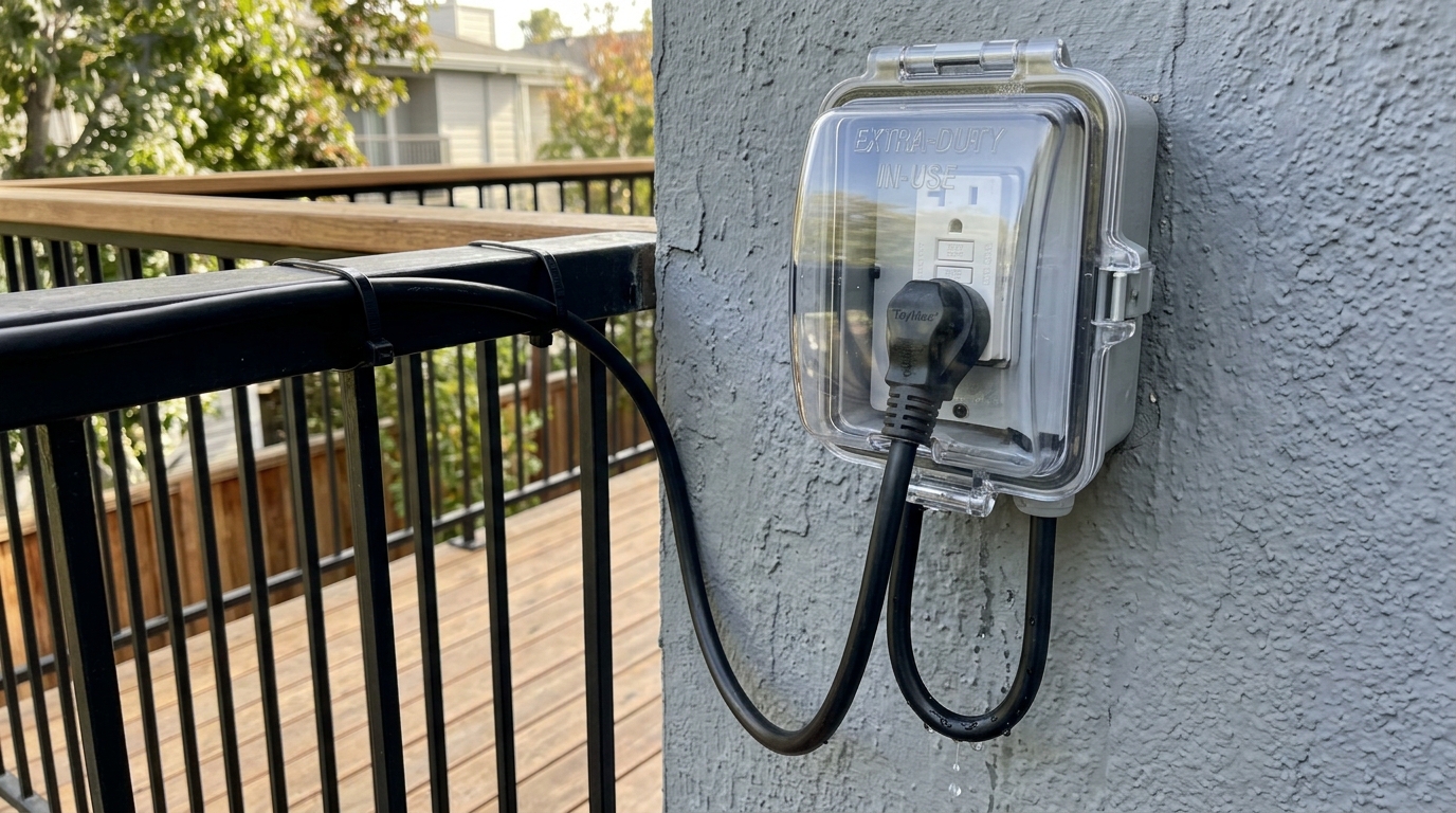 Code-compliant exterior installation. An extra-duty while-in-use bubble cover
shields the outdoor receptacle, paired with a downward U-shaped drip loop that sheds
rainwater safely before the cable enters the enclosure. Photo: BalconySolar.org.
Code-compliant exterior installation. An extra-duty while-in-use bubble cover
shields the outdoor receptacle, paired with a downward U-shaped drip loop that sheds
rainwater safely before the cable enters the enclosure. Photo: BalconySolar.org.
Form a drip loop by letting the microinverter AC cord dip 3 to 4 inches below the level of the outdoor outlet before curving upward into the receptacle. Water pools at the lowest bend and drips harmlessly to the balcony deck.
Secure the cable along your railing with UV-resistant, stainless steel or heavy-duty nylon cable ties. Fastening the wire every 18 inches prevents gusty winds from tugging against the wall socket.
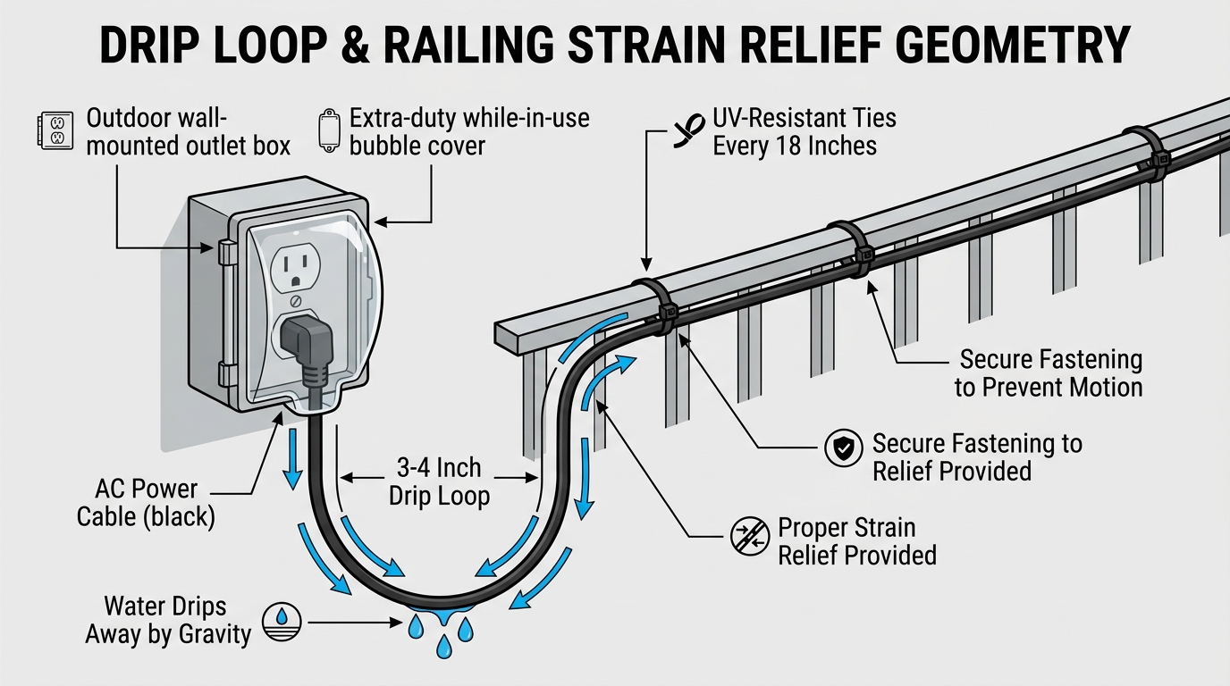 Drip loop and railing strain relief geometry. The microinverter cable dips 3 to 4
inches below the outlet enclosure so rainwater sheds harmlessly by gravity before
reaching electrical contacts. UV-resistant cable ties fastened every 18 inches
prevent mechanical wind strain on the receptacle. Diagram: BalconySolar.org.
Drip loop and railing strain relief geometry. The microinverter cable dips 3 to 4
inches below the outlet enclosure so rainwater sheds harmlessly by gravity before
reaching electrical contacts. UV-resistant cable ties fastened every 18 inches
prevent mechanical wind strain on the receptacle. Diagram: BalconySolar.org.
Upgrade 6: Dedicated 20 A branch circuit ($150 to $350)
For homeowners or long-term residents seeking maximum capacity, hire a licensed electrician to pull a dedicated 20 A circuit with 12 AWG wiring from the panelboard to the balcony.
A dedicated circuit serves only the solar microinverter. This eliminates all shared-load conductor concerns. Neither Colorado’s HB26-1007 nor Utah’s HB 340 requires a dedicated circuit.
7. Step-by-step pre-connection inspection checklist
Download and print our official Landlord & HOA Safety Handout for architectural reviews and property manager sign-offs.
Follow this practical six-step procedure before energizing your balcony solar kit:
Step 1: Inspecting the outdoor receptacle and enclosure
Verify that the outdoor electrical box is firmly anchored to the exterior wall. Check that the perimeter caulking remains intact to block moisture behind the siding.
Step 2: Testing outlet polarity and ground continuity
Insert your circuit analyzer into the socket. Confirm two amber lights illuminate, indicating correct wiring and solid ground bonding.
Step 3: Verifying GFCI tripping speed
Press the test button on your GFCI outlet or tester. Confirm the reset button pops out with an audible click and power cuts out immediately. Press reset to restore power.
Step 4: Installing the extra-duty bubble cover
If your box lacks a deep while-in-use cover, shut off the breaker, unscrew the old plate, and mount a certified extra-duty polycarbonate enclosure.
Step 5: Routing cabling with drip loop and conduit protection
Route the AC cable securely along railing balusters or inside protective conduit across yard paths. Secure the cord with UV-rated ties and form a 4-inch downward drip loop below the receptacle entrance.
Step 6: Connecting equipment and monitoring initial boot
Insert the three-prong plug firmly into the receptacle and close the bubble cover. Observe the LED indicator on the microinverter: a solid or pulsing green light confirms successful grid synchronization within one to two minutes.
Code references and technical standards
-
NFPA 70: National Electrical Code (NEC):
- Section 406.9(B)(1): Receptacles in Damp or Wet Locations (Extra-Duty While-in-Use Enclosures).
- Section 210.8(A)(3): Ground-Fault Circuit-Interrupter Protection for Dwelling Unit Outdoor Outlets.
- Section 400.12: Uses Not Permitted for Flexible Cords and Cables.
- Section 240.4(D): Small Conductor Overcurrent Protection (14 AWG 15 A / 12 AWG 20 A limits).
- Section 705.12: Point of Connection and Supply-Side/Load-Side Interconnection Rules.
- Section 300.5: Underground Installations (Minimum Cover Requirements for Outdoor Wiring).
- Section 690.31: Methods for Photovoltaic Wiring (Mechanical Protection of PV Conductors).
-
Underwriters Laboratories (UL):
- UL 1741 / UL 1741-SB: Standard for Inverters, Converters, Controllers and Interconnection System Equipment.
- UL 498: Standard for Attachment Plugs and Receptacles (Weather-Resistant WR Rating).
- UL 943: Standard for Ground-Fault Circuit-Interrupters.
-
Institute of Electrical and Electronics Engineers (IEEE):
- IEEE 1547-2018: Standard for Interconnection and Interoperability of Distributed Energy Resources with Associated Electric Power Systems Interfaces.
-
National Electrical Manufacturers Association (NEMA):
- NEMA WD 6: Wiring Devices Dimensional Specifications (NEMA 5-15 and 5-20 Receptacles).
Disclaimer: This guide is provided for educational purposes and summarizes standard electrical best practices. It does not replace professional electrical engineering or local building codes. Always inspect wiring carefully and consult a licensed electrician if you observe damaged receptacles, ungrounded circuits, or persistent GFCI trips.