
Direct Answer (TL;DR)
MPPTMaximum Power Point Tracking (MPPT)High-frequency DC-to-DC conversion circuitry that dynamically modulates electrical impedance to keep photovoltaic modules operating at peak power output.Explore System Simulator → is automated circuitry inside a microinverterMicroinverterA compact grid-tied power converter mounted directly behind solar modules that converts low-voltage DC to household 120V AC.UL 1741 Safety Guide → that continuously adjusts circuit impedance to find the exact combination of voltage and current where panels generate maximum wattage.
Changing sunlight intensity and outdoor temperatures shift the solar cell power curve hundreds of times per day. Without tracking, a static load forfeits 20% to 40% of annual generation, per the NREL MPPT Efficiency Analysis. For balcony railings, dual independent MPPT channels are essential. When an architectural overhang, railing baluster, or plant shades one module, its dedicated tracker isolates the loss. This allows the companion panel to produce at full capacity without interference.
Balcony solar systems operate in dynamic, microclimatic environments. Unlike large utility-scale solar farms installed in open deserts, apartment solar panels contend with urban shading, vertical mounting angles, ambient heat reflection from concrete walls, and changing weather conditions throughout the day.
Despite these environmental challenges, modern plug-in microinverters extract high energy yields from modest two-panel arrays. The core engineering technology responsible for this efficiency is Maximum Power Point Tracking (MPPT).
This guide explains photovoltaic power curves and examines how microinverter tracking algorithms operate in real time. It details why dual independent MPPT trackers are indispensable for apartment balconies and how circuitry protects systems during overpanelling.
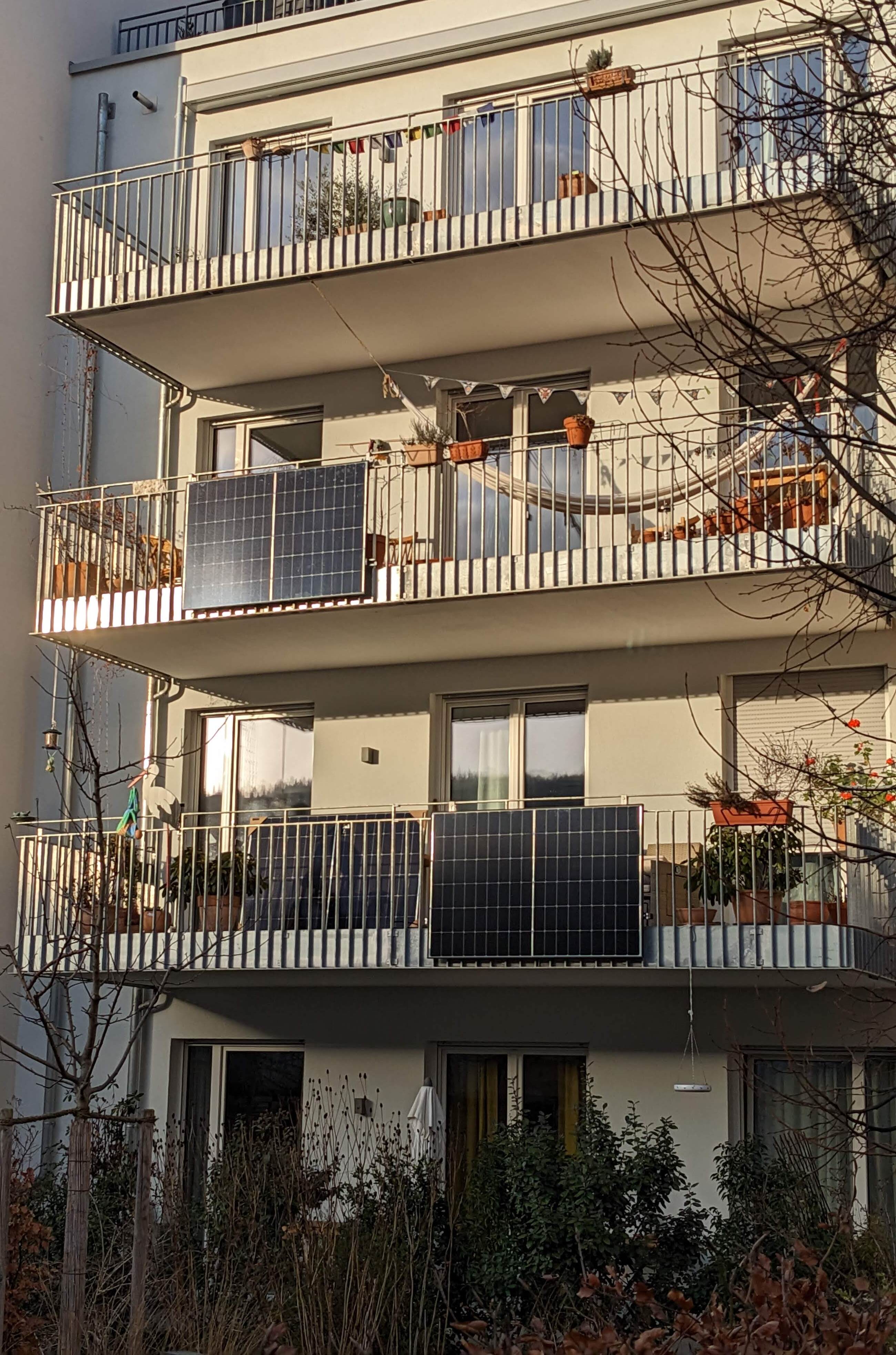 Balcony solar arrays require intelligent MPPT tracking to harvest maximum power
despite variable angles and urban micro-shading. Photo: BalconySolar.org.
Balcony solar arrays require intelligent MPPT tracking to harvest maximum power
despite variable angles and urban micro-shading. Photo: BalconySolar.org.
1. Photovoltaic physics and the non-linear IV curve
To understand why tracking is necessary, one must look at how solar cells generate electricity. Solar cells do not behave like simple batteries or fixed resistors. A battery maintains a relatively stable voltage as load changes; a resistor draws current strictly proportional to applied voltage (I = V/R).
Photovoltaic cells, by contrast, are non-linear semiconductor diodes that function as light-generated current sources. Their performance is described by an IV curve (Current versus Voltage) and a corresponding PV curve (Power versus Voltage):
Current (A)
 ^
 |-----------------\
 |                  \
 |  Constant Current \
 |      Region        \ Knee Point: Vmp, Imp (Maximum Power)
 |                     \
 |                      \
 |                       \  Rapid Voltage Drop
 |                        \
 +-------------------------\--------> Voltage (V)
 0                         Voc
Key reference points govern this electrical relationship:
- Short-Circuit Current (Isc): The maximum current generated when the positive and negative terminals are shorted together (V = 0). Power output is zero (0 V × Isc = 0 W).
- Open-Circuit Voltage (Voc): The maximum voltage across the terminals when no current is flowing (I = 0). Power output is again zero (Voc × 0 A = 0 W).
- Maximum Power Point (Pmp): The specific operational point on the “knee” of the curve where the product of voltage and current reaches its mathematical absolute peak (Pmp = Vmp × Imp).
If an inverter applied a fixed 30 V load to a panel whose peak power voltage had dropped to 26 V due to summer heat, current collection would collapse. Conversely, drawing too much current pushes the voltage below the knee, precipitating a steep drop in total output.
How environmental factors shift the curve
The Maximum Power Point is not a stationary target. It shifts continuously throughout the day in response to two primary environmental variables:
- Solar Irradiance (Sunlight Intensity): Current (I) is directly proportional to solar irradiance. On a bright, clear midday with 1, 000 W/m2 of sunlight, a typical 400 W module might deliver 13 A. Under cloud cover or early morning light (200 W/m2), output current drops to 2.6 A. Voltage changes only modestly with irradiance, shifting the knee primarily along the vertical axis.
- Cell Temperature: Silicon solar cells have a negative temperature coefficient for voltage, evaluated under the NREL Photovoltaic Module Testing Procedures. Under standard test conditions (STC, 25 deg C / 77 deg F), a panel specifies a Vmp of 32 V. In summer, dark panel surfaces on a sunny balcony reach 65 deg C (149 deg F). With a typical negative coefficient of 0.30% per deg C, operational voltage drops by 12% to roughly 28 V.
Without continuous tracking, fixed-voltage hardware leaves significant energy unharvested during cool mornings and hot afternoons alike.
2. How microinverter MPPT algorithms work
An MPPT controller is essentially a high-frequency, digitally controlled DC-to-DC switch-mode power converter (typically a buck-boost or boost topology). By modulating the duty cycle of its high-speed semiconductor switches (MOSFETs or GaN transistors) at frequencies between 50 kHz and 200 kHz, the inverter dynamically adjusts the effective electrical resistance presented to the solar panel.
The controller samples voltage and current thousands of times per second and executes sophisticated digital algorithms to locate and maintain the maximum power point.
+-------------+      +-------------------+      +------------------+      +-------------+
| Solar Panel | ---> | DC-DC Converter   | ---> | DC-AC Inverter   | ---> | 120V AC Plug|
| (DC Output) |      | (MPPT Modulation) |      | (Grid Sync & UL) |      | (Household) |
+-------------+      +-------------------+      +------------------+      +-------------+
       |                       ^
       v                       | Duty Cycle
+------------------------------+
| Microcontroller (P&O / IncCond)
+------------------------------+
Perturb and Observe (P&O)
The most widespread algorithm in commercial microinverters is Perturb and Observe (P&O), also known as hill climbing. The operational logic follows three structured steps:
- The controller measures current panel power: P1 = V1 × I1.
- It introduces a small perturbation by adjusting operating voltage slightly upward (V2 = V1 + ΔV).
- It measures the new power output: P2 = V2 × I2.
-
Decision:
- If P2 > P1, the controller moved in the correct direction (up the power hill). The next perturbation will also increase voltage.
- If P2 < P1, the controller moved away from the peak (down the power hill). The controller reverses direction and decreases voltage on the next step.
Under steady illumination, the algorithm oscillates gently around the actual maximum power point. Modern microinverters use adaptive step sizes (ΔV): taking larger steps when far from the knee to respond quickly to clearing clouds, and minute steps near the summit to minimize tracking ripple.
Incremental Conductance
High-tier microinverters employ Incremental Conductance, which evaluates the mathematical derivative of power with respect to voltage (dP/dV):
$$\frac{dP}{dV} = \frac{d(VI)}{dV} = I + V \frac{dI}{dV}$$
At the exact peak of the power curve, the slope is zero (dP/dV = 0):
$$\frac{dI}{dV} = -\frac{I}{V}$$
By comparing instantaneous conductance (I/V) with incremental conductance (dI/dV), the microinverter determines whether it is at the peak, to the left, or to the right without continuous hunting oscillations. This provides tracking stability under rapidly fluctuating skies.
Under the EN 50530 Dynamic MPPT Efficiency Standards, certified microinverters achieve tracking efficiencies exceeding 99.5%, meaning less than half of one percent of potential solar energy is lost to tracking latency.
3. Why dual independent MPPT is essential for balcony arrays
In conventional rooftop solar installations, multiple modules are wired in series to form a high-voltage string connected to a central inverter. If all panels face the same direction on an open, unshaded roof, a single MPPT tracker performs adequately.
For balcony solar, however, a single tracker or series wiring introduces severe production bottlenecks. Certified balcony microinverters (such as the Hoymiles HMS-800, APsystems EZ1-M, TSUN MS800, or Anker SOLIX MI80) feature two independent DC inputs, each governed by its own dedicated MPPT channel.
The table below contrasts single-tracker limitations with dual-tracker performance on an apartment railing:
| Scenario / Condition | Single MPPT / Series Wiring | Dual Independent MPPT Channels |
|---|---|---|
| Partial Baluster Shade | Shading on one panel drags down total string output | Shaded panel adjusts; companion panel produces at full potential |
| Corner Balcony Layout | East and South panels drag each other down; mismatch losses | Each orientation tracks its own distinct sun angle |
| Panel Soiling / Dirt | Dirtiest cell limits string current | Loss restricted exclusively to the soiled module |
| Different Panel Brands | Forced compromise voltage and current ratings | Complete freedom to mix different panel wattages |
| Hardware Capital Cost | Slightly cheaper circuit design | Standard on certified 800 W dual-input microinverters |
The physics of partial shading on a railing
Balcony railings present unique micro-shading obstacles. Vertical baluster spindles, solid privacy dividers, upper-floor balcony overhangs, and exterior masonry pilasters cast sharp shadows across panels at specific hours.
When a single solar cell within a module is shaded, it ceases to generate electricity and instead becomes a resistive load. If forced to conduct current produced by adjacent unshaded cells, the shaded cell dissipates energy as heat, creating hot spots that can permanently damage protective EVA encapsulant layers.
To prevent destructive overheating, panels include internal bypass diodesBypass DiodeAn electrical diode connected in parallel with cell substrings that conducts current around shaded cells to prevent hot spots and total string collapse.Panel Selection Guide →. A standard 400 W module typically contains three diodes, dividing the panel into three vertical or horizontal cell substrings.
When a shadow strikes one substring, its bypass diode forward-biases, allowing current to bypass the shaded cells. However, this abruptly drops module voltage by approximately one-third (about 10 V).
Unshaded Panel A: 32V @ 12A = 384W
Partially Shaded Panel B (1 string bypassed): 21V @ 12A = 252W

Under Single Shared MPPT:
Inverter must pick one compromise voltage. Total output: ~450W.

Under Dual Independent MPPT:
Tracker 1 locks onto 32V / 12A -> 384W
Tracker 2 locks onto 21V / 12A -> 252W
Total system output: 636W (+41% higher yield)
With dual MPPT, Channel 1 continues operating at 32 V while Channel 2 independently locks onto 21 V. The system harvests 636 W rather than collapsing to a compromise 450 W. For a deeper analysis of shade mitigation, see our guide on balcony solar shade and north-facing fit.
Multi-peaked P-V curves, local maxima trapping, and global sweeps
Bypass diode activation solves the cell-level hot-spot problem, but it introduces a major tracking challenge: multi-modal power-voltage curves.
When an unshaded panel is illuminated uniformly, its power-voltage (P-V) curve displays a single, smooth hill with one distinct peak (a unimodal curve). However, when balusters, railings, or adjacent walls partially shade a panel and bypass diodes begin conducting around shaded substrings, the P-V curve fractures into multiple peaks:
Power (W)
 ^
 |             Global Maximum (GMPP)
 |                   /\
 |                  /  \
 |                 /    \
 |   Local Peak   /      \
 |     (LMPP)    /        \
 |       /\     /          \
 |      /  \   /            \
 |     /    \_/              \
 +----+------+----------------\--------> Voltage (V)
 0    0.3 Vmp                 Vmp      Voc
On a multi-modal curve, there is one Global Maximum Power Point (GMPP) and one or more inferior Local Maximum Power Points (LMPP):
- The Hill-Climbing Trap: Standard Perturb and Observe (P&O) and basic Incremental Conductance algorithms are local optimizers. They evaluate only the immediate slope (dP/dV) of the operating point. If an algorithm encounters sudden shading while tracking, it can climb the smaller local hill (LMPP) and stop at its peak where dP/dV = 0. The controller assumes it has found the maximum output and oscillates there, unable to detect that a larger peak exists at a higher voltage.
- Quantifying the Shade Harvest Loss: Per NREL Photovoltaic Partial Shading Field Studies, an inverter trapped at an LMPP extracts only 100 W to 120 W from a panel capable of 280 W at its GMPP. This forfeits over half of harvestable solar energy during shade events.
- Firmware Mitigation: Global MPPT (GMPPT) Sweeping: To prevent local maxima trapping, modern microinverter firmware includes Global MPPT (GMPPT) sweeping routines. At periodic intervals, typically every 5 to 15 minutes, the microinverter initiates a rapid wide-voltage scan. Over a few hundred milliseconds, it sweeps its operating point across the entire input voltage window from minimum operating voltage to Voc. It measures the full curve profile, identifies the true GMPP coordinates, and re-anchors the high-frequency tracker onto the global summit.
4. How MPPT manages overpanelling without overloading
A common concern among beginners is overpanelling: connecting solar panels with a combined DC rating greater than the inverter AC output limit (for example, pairing two 500 W panels with an 800 W microinverter).
Homeowners often worry: Will connecting 1,000 W of panels force excessive current into an 800 W inverter and cause an electrical fire or blown fuses?
The answer is no, because of how MPPT controllers manage electrical intake. Power is not “pushed” by solar panels into an inverter; it is drawn by the inverter based on its internal MPPT settings.
Current (A)
 ^
 |
 |---------\  Full Sunlight Potential: 500W per module (15.6A @ 32V)
 |          \
 |...........\................................ Maximum Inverter Current Limit: 12.5A
 |            \  Operating Point Shifted:
 |             \ Inverter raises voltage to 34V, drawing only 11.8A (400W AC limit)
 |              \
 +---------------\-----------------------------> Voltage (V)
 0               Vmp                         Voc
Current clipping vs voltage limits
To understand equipment safety during overpanelling, one must distinguish between voltage and current limits:
- Current Is Actively Controlled (Current Clipping): Microinverters specify a Maximum Continuous Input Current (Idc, max), typically 14 A to 16 A per MPPT input. If an oversized panel generates 18 A at peak noon, the MPPT controller simply increases its effective impedance. By shifting its operating point slightly up the voltage curve toward Voc, it limits intake current to exactly 14 A. The excess potential energy remains unharvested as mild surface warmth on the panel glass.
- Voltage Is a Hard Physical Ceiling: While current is safely throttled by MPPT logic, input voltage is an absolute physical limit. If open-circuit voltage (Voc) exceeds the inverter maximum rating (typically 60 V DC), the excessive electrical pressure will puncture internal input capacitors and destroy power switching stages, even if the inverter is idle.
Because cold winter mornings increase open-circuit voltage (Voc rises as temperatures drop), buyers must verify that the cold-weather temperature-adjusted Voc of their panels remains below the 60 V limit. In balcony systems, standard 108-half-cell or 120-half-cell panels have a Voc around 37 V to 44 V, comfortably within safe operational thresholds.
For detailed formulas on sizing DC/AC ratios for extended morning and evening harvest, consult our balcony solar overpanelling guide.
5. Microinverter MPPT technical specifications and hardware comparison
When evaluating microinverters for a balcony solar installation, review the manufacturer specification sheet for the following critical parameters:
- MPPT Voltage Range (e.g., 16 V to 60 V): The full voltage window over which the tracker can operate. Wider ranges ensure power harvesting continues during overcast weather when module voltage dips.
- Full Power MPPT Voltage Range (e.g., 28 V to 45 V): The narrower voltage band within which the inverter can deliver its rated maximum AC wattage. Selecting panels whose nominal Vmp sits centrally in this range (typically 30 V to 34 V for modern residential modules) guarantees maximum energy yield.
- Startup Voltage (e.g., 16 V to 22 V): The minimum DC voltage required to wake the internal microcontroller and initiate grid synchronization. Lower startup thresholds enable earlier morning startup and later evening shutdown.
- Number of MPPT Trackers: Ensure the device provides independent MPPT trackers per panel, rather than multiple inputs internally paralleled into a single tracker.
- Maximum Input Current (Idc, max) and Short-Circuit Current (Isc, max): The continuous current limit and maximum fault current the input stage can safely handle.
Comparative specifications of leading microinverter families
The table below contrasts the MPPT specifications and architectural features of the four leading microinverter families used in residential and balcony solar:
| Feature / Parameter | Hoymiles HMS-800-2T | APsystems EZ1-M | Enphase IQ8 Series (IQ8+) | EcoFlow PowerStream |
|---|---|---|---|---|
| MPPT Channels | 2 independent trackers | 2 independent trackers | 1 tracker per microinverter | 2 independent trackers |
| Max AC Output | 800 W (dual 400 W) | 800 W (switchable to 600 W) | 300 VA (per unit, gangable) | 800 W (dual 400 W) |
| MPPT Voltage Range | 16 V to 60 V | 16 V to 60 V | 16 V to 45 V | 11 V to 55 V |
| Full Power MPPT Band | 32 V to 55 V | 28 V to 45 V | 29 V to 45 V | 15 V to 55 V |
| Startup Voltage | 22 V | 16 V | 22 V | 11 V |
| Max DC Input Voltage (Vmax) | 60 V | 60 V | 60 V | 55 V |
| Max Continuous Input Current (Idc, max) | 14 A per channel | 20 A per channel | 12 A (module level) | 13 A per channel |
| Max Short-Circuit Current (Isc, max) | 25 A per channel | 25 A per channel | 15 A | 14 A per channel |
| Battery Bus Integration | AC-coupled via external storage | AC-coupled via external storage | Enphase IQ Battery integration | Direct DC battery bus (XT150) |
| Communication / Telemetry | Sub-1 GHz RF to DTU / Cloud | Direct Wi-Fi + Bluetooth (Local API) | Power Line Communication (Envoy) | Wi-Fi + Bluetooth (EcoFlow App) |
Manufacturer architectural profiles
Hoymiles HMS-800-2T
Hoymiles is widely deployed in European plug-in solar installations. The HMS-800-2T houses two completely independent MPPT tracking channels within a sealed cast-aluminum IP67 enclosure. Each channel supports up to 14 A continuous operating current, making it fully compatible with modern 182 mm and 210 mm half-cell silicon wafers. Its wide 16 V to 60 V operational span provides dependable overcast harvesting, and its Sub-1 GHz RF communication delivers channel-isolated DC metrics without crowding home 2.4 GHz Wi-Fi spectrum.
APsystems EZ1-M
The APsystems EZ1-M provides an industry-leading 20 A continuous input current limit per MPPT channel. This generous current headroom allows heavy overpanelling with 500 W bifacial modules without triggering premature thermal current throttling. Uniquely, the EZ1-M incorporates local Bluetooth and Wi-Fi direct communication. Home automation platforms can poll real-time DC voltage, DC current, and power metrics via a local HTTP API without requiring an active external cloud connection.
Enphase IQ8 Series (IQ8+, IQ8M, IQ8A)
Enphase employs a decentralized 1-to-1 modular architecture. Rather than connecting two panels to a dual-input inverter, each individual solar module connects to its own dedicated IQ8 microinverter. This eliminates DC wiring runs between panels and provides complete granular MPPT isolation. The IQ8 features a proprietary ASIC with microsecond-level grid synchronization and UL 1741-SB compliance built directly into the silicon. For balcony installations where two modules sit far apart, pairing two IQ8 microinverters on a shared AC branch provides shade isolation.
EcoFlow PowerStream
The EcoFlow PowerStream represents a hybrid DC-coupled architecture designed specifically for apartment renters seeking night-time battery usage. In addition to two independent MPPT inputs (11 V to 55 V, 13 A each), the PowerStream features a dedicated bidirectional DC battery port. This port connects directly to EcoFlow portable power stations via an XT150 cable. During peak solar hours, the internal MPPT controller dynamically routes DC solar electricity straight into the battery pack before converting it to AC. This avoids the round-trip conversion losses typical of traditional AC-coupled battery chargers. In the evening, the microinverter draws energy from the battery pack and injects a steady baseline onto household circuits.
To calculate expected annual production, financial payback timelines, and local utility bill offsets based on your state irradiance and electricity rates, use our interactive balcony solar system simulator.